
Introduction
I was previously using TP-LINK TL-WR740N v4 as my home router/switch/AP. It is cheap (about 25$) and does not provide too much features but it certainly works well and is enough for an average home user. I needed something that I could play with a lot more, something that could give me more control over my internet connection, provide logging capabilites, advanced routing, firewall, qos and security enhancements. All I really needed for this is just a linux box. There are readily available open source applications that could provide me with all these features. Of course it’s not plug-and-play solution and it needs a lot of insight and tinkering but that’s just the fun part for me.
Hardware
What I needed was a small, not-power-hungry, quiet and cheap linux server. It should preferably have 2 ethernet ports and built-in wifi (or at least pci or usb ports so I could plug additional interface cards). I considered mini-ITX mainboard based server as it would give me most flexibility and even possibility to run virtualization on x86 CPU with support for hardware virtualization and 2 HDDs for RAID 1. I didn’t go for it because I didn’t want to spend so much money plus it would most likely be actively cooled which would generate noise. Then my eyes turned to Raspberry Pi, which is a very cheap and small ARM-based computer. The main caveat of it is that it only has one FastEthernet port which makes it not very suitable for a router. You can add additional ethernet port as an USB adapter (or wifi adapter). However, I didn’t like the idea to add two USB adapters to have a complete router with AP. I also found more expensive alternative of Raspberry Pi called Utilite which would be just perfect as it has 2 x GbE ports plus Wifi built-in, but again the cost was much higher (plus shipping costs from Israel). That’s why I decided to work with what I have creating low-cost solution.
Architecture
The idea is to use TP-Link TL-WR740N as a switch and access point and Raspberry Pi as router. To accomplish that with only one FastEthernet port I would need VLAN support on the switch to deploy something called “router on a stick”.
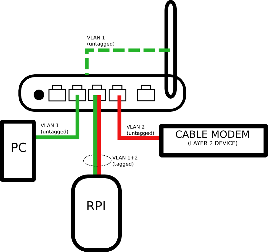
VLANs allow you to create logically separated layer 2 networks. Without VLANs all ports on the switch belong to one logical network and frames sent from one port can freely travel to any other port. However if you put ports in separate VLANs then traffic from one VLAN can’t go to another VLAN without a router.
Cable modem connects you to the provider (it could as well be ADSL modem or radio antenna) and forwards L2 frames to the VLAN 2 (the numbers are arbitrary). If your modem already has a router built in then you can still use this topology but you will most likely have to double NAT. Frames which are untagged simply do not carry VLAN information within them. The switch recognizes which VLAN they belong to because the port is statically configured to be a member of specific VLAN. Switch port that has raspberry PI connected is a member of two VLANs (it is also called trunk port). Frames transmitted across this interface are tagged which means they contain VLAN infromation. That way router and the switch are able to tell which VLAN the frame belongs to.
When you receive a packet from the internet it travels through the modem, VLAN2 port, comes into raspberry PI via trunk port, RPI deals with routing, NAT and other functions that you implement, comes out of the same port (but this time via VLAN 1) and is forwarded to the PC or WiFi client which also belong to the VLAN1. Please note that the traffic needs to pass the trunk interface twice (once in inbound direction and once in outbound direction). This has performance implications. You can think of it as the half-duplex port even though it’s full-duplex port physically. When you download something from the internet with 100Mbps speed (the speed of RPI and TP-LINK WR740N ports) you can do this but it will also take up “upload” of the port. In other words your upload+download speed is capped at 100Mbps but I don’t think it’s the problem for most home users.
Switch configuration
Installation
Note that there is no Web interface by default for TP-LINK WR740N openwrt images.
http://wiki.openwrt.org/doc/howto/generic.flashing gives you a generic explanation of the installation process. You will not need most of the information given there. Let me walk you through the installation:
1. Identify your exact model (there are versions 1,2,3 and 4). http://wiki.openwrt.org/toh/tp-link/tl-wr740n can give you some useful information. Please note that there is “debricking” section in case something goes wrong. I did not need to do this but if you lose connectivity to your router you can find out how to get it back online in this section.
2. Download firmware from http://downloads.openwrt.org/attitude_adjustment/12.09/ar71xx/generic/
I used http://downloads.openwrt.org/attitude_adjustment/12.09/ar71xx/generic/openwrt-ar71xx-generic-tl-wr740n-v4-squashfs-factory.bin
There are “JFFS2” and “squasfs” versions. I am not sure what is the difference. Squashfs is recommended. “Factory” is for installing openwrt on router with factory image and “sysupgrade” is for upgrading.
3. Reset TP-LINK to factory defaults.
4. Use Firmware Upgrade function and select image of OpenWrt.
5. After the router reboots telnet to the address 192.168.1.1. There is no password.
6. Use command “passwd”. It will prompt you to choose your root password. After you choose it telnet will be disabled and SSH will be enabled. Type “exit”.
7. Log in with your chosen password on “root” account using SSH. You can now configure your OpenWrt device.
Network configuration
All the interesting configuration is in the directory /etc/config.
Network configuration is stored in /etc/config/network. Let’s view the defaults.
config interface 'loopback'
 option ifname 'lo'
 option proto 'static'
 option ipaddr '127.0.0.1'
 option netmask '255.0.0.0'

config globals 'globals'
 option ula_prefix 'fd9c:6323:7240::/48'

config interface 'lan'
 option ifname 'eth0'
 option type 'bridge'
 option proto 'static'
 option ipaddr '192.168.1.1'
 option netmask '255.255.255.0'
 option ip6assign '60'

config interface 'wan'
 option ifname 'eth1'
 option proto 'dhcp'

config interface 'wan6'
 option ifname '@wan'
 option proto 'dhcpv6'

config switch
 option name 'switch0'
 option reset '1'
 option enable_vlan '1'

config switch_vlan
 option device 'switch0'
 option vlan '1'
 option ports '0 1 2 3 4'
- config interface ‘lan’ s section is pretty straifghtforward. You can set ip address and netmask of lan interface of your TP-LINK router.
- config switch section is misleading. I would expect that you need to enable additional VLANs here but this is not the case. You don’t need to do anything here. I don’t know what it’s for.
- config switch_vlan
This is where you’ll be configuring VLAN settings. If you need to add additional VLAN just add another config switch_vlan section (identical section name). Leave the option device ‘switch0’ as is. Specify which VLAN you want to configure in option vlan.
Option ports is a list of physical and logical ports that are members of the VLAN. If you use number alone like 1,2,3 and so on it means that the VLAN will be untagged on that port (of course you can have only one untagged VLAN on port). If you append letter “t” to the number it will tag the frames of that VLAN on that port.
Port numbering
0 – logical port that connects the switch to the CPU of the device. You will only need to add VLAN to this interface when you need to manage the device using IP from that VLAN or if you want it to provide services like DHCP or DNS on that VLAN. We will add VLAN 1 (which coressponds to LAN) to the port 0 untagged.
1,2,3,4 – physical ports
Please note the numbering is not in order!

If you are unsure which ports are you configuring or you find this information incorrect you can display which ports are currently up/down by issuing command:
swconfig dev switch0 show
This is the configuration that I use:
config interface 'loopback'
option ifname 'lo'
option proto 'static'
option ipaddr '127.0.0.1'
option netmask '255.0.0.0'

config globals 'globals'
option ula_prefix 'fd9c:6323:7240::/48'

config interface 'lan'
option ifname 'eth0'
option type 'bridge'
option proto 'static'
option ipaddr '192.168.33.254'
option netmask '255.255.255.0'
option ip6assign '60'

config interface 'wan'
option ifname 'eth1'
option proto 'dhcp'

config interface 'wan6'
option ifname '@wan'
option proto 'dhcpv6'

config switch
option name 'switch0'
option reset '1'
option enable_vlan '1'

config switch_vlan
option device 'switch0'
option vlan '1'
option ports '0 1 3t 4'

config switch_vlan
option device 'switch0'
option vlan '2'
option ports '2 3t'
As you can see port 3 is being being used as trunk and will be connected to RPI. Port 2 will be connected to WAN and port 1 and 4 will be LAN ports. I will not be using eth1 which is normally WAN port when using stock firmware.
Optional
If you want to create multiple IP interfaces (one for each VLAN) you can just add another config interface section and specify ifname as eth0.N where N is VLAN number. Example:
config interface 'lan2'
option ifname 'eth0.2'
option type 'bridge'
option proto 'static'
option ipaddr '192.168.2.1'
option netmask '255.255.255.0'
Don’t forget to add tagged VLAN to the port 0!
Wireless
Wifi is disabled by default on openwrt. The relevant configuration file is /etc/config/wireless. In order to enable the wireless you need to set option disabled to 0 (or remove the line).
The most popular,secure and completely sufficient configuration for home users is just WPA2-encrypted connection using pre-shared key.
Sample configuration is here:
config wifi-device radio0
 option type mac80211
 option channel 1
 option hwmode 11ng
 option path 'platform/ar933x_wmac'
 option htmode HT20
 list ht_capab SHORT-GI-20
 list ht_capab SHORT-GI-40
 list ht_capab RX-STBC1
 list ht_capab DSSS_CCK-40
 # REMOVE THIS LINE TO ENABLE WIFI:
 option disabled 0

config wifi-iface
 option device radio0
 option network lan
 option mode ap
 option ssid your_ssid_here
 option encryption psk2
 option key your_password_here
Disable unnecessary services
RPI will provide DHCP and DNS services for our network. You certainly do not want two DHCP servers running concurrently in your LAN. Daemon which is responsible for both of these functions is called dnsmasq. To prevent it from starting automatically after reboot type:
/etc/init.d/dnsmasq disable
Apply settings
After all configuration changes you can just reboot your router and hope you do not cut yourself out of management:
reboot
Final words
This was first part of the tutorial. I will add routing part which is more interesting soon!